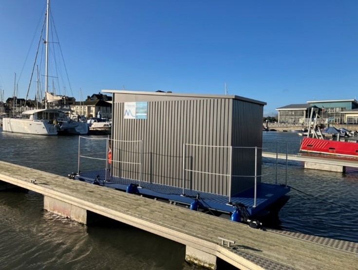
DCU team deploys a test platform to carry out dynamic antifouling tests in Dublin Bay
NEMMO partner, the DCU Water Institute and the Schools of Mechanical and Manufacturing Engineering and Chemical Sciences, developed and commissioned a marine platform to test the antifouling performance of novel marine coatings and textures. The platform was designed to recreate conditions similar to those experienced over the active surface of marine hydro-kinetic turbines. It relied on a vertical axis 1.2 m diameter two blade rotor which can accommodate 12 rectangular samples of dimensions 4×34 cm.
The samples were secured into a one of four recesses on each of the exposed and flat surfaces of the blade so that they were aligned with the straight leading edge. Hydrodynamic surface stresses predicted by Computational Fluid Dynamics simulations were shown to increase radially with little dependence on the circumferential position, so that all samples were subjected to similar conditions. At the maximum rotational speed of , the samples were exposed to stresses varying from approximately 20 N/m2 at the lower radial position r=25.5 cm to a maximum of approximately at the sample tip.
Four anti-fouling coatings and one biomimetic texture were tested at a deployment site on the east coast of Ireland. The site is a commercial marina located in the outer Broadmeadow estuary of North County Dublin (Figure 1 and Figure 2).
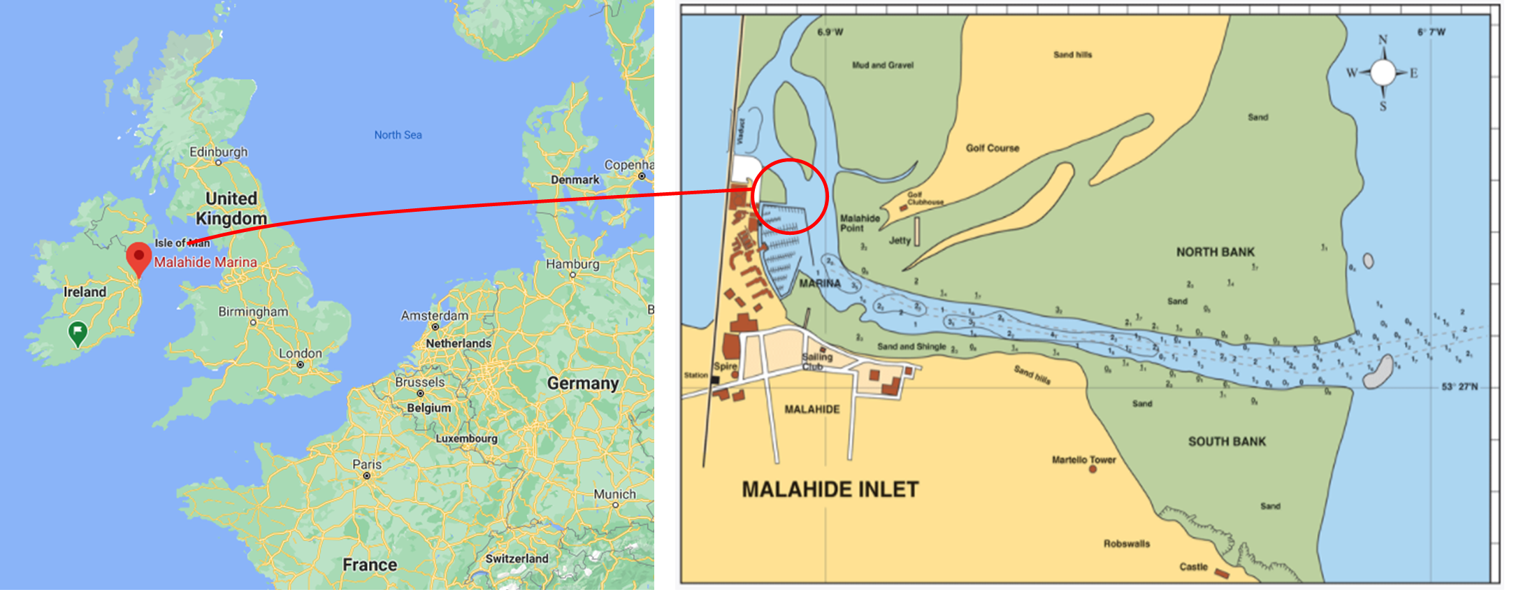
Figure 1 Location of deployment at broadmeadow estuary, Ireland.
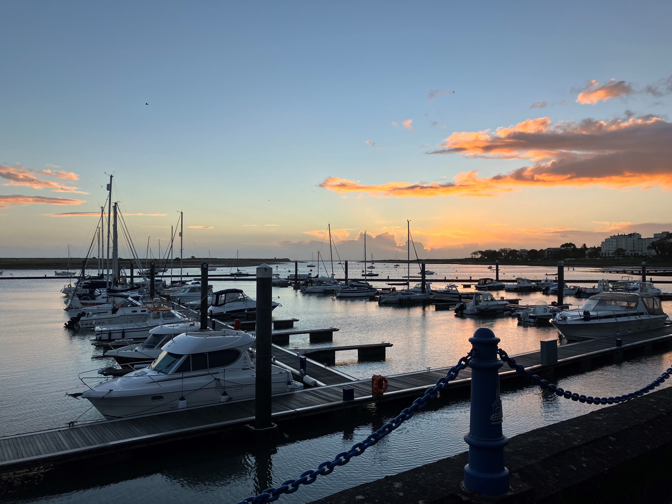

Figure 2 Images of platform at deployment site
Separate samples were immersed under static and dynamic conditions. For the dynamic tests, the turbine was rotated at , over a period of 30 minutes once a day while both sets of samples are exposed to the tidal currents. The test was continued over a period of 8.5 months to include the period of highest biomass production in the region. Microscopic imaging was used to monitor the evolution of biofouling starting from initial attachment of individual micro-organisms. Sample raw images obtained from the gel coated and micro-textured material samples are shown in Figure 3.
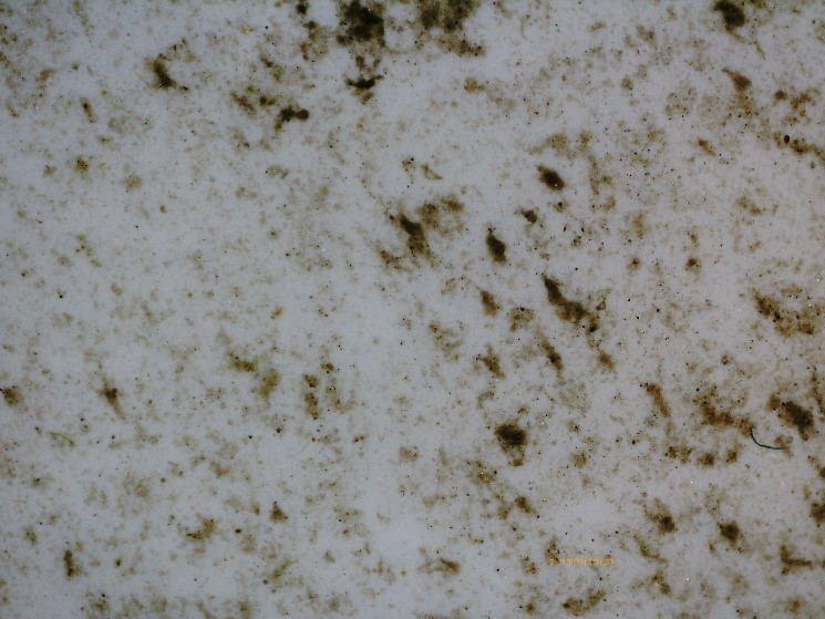
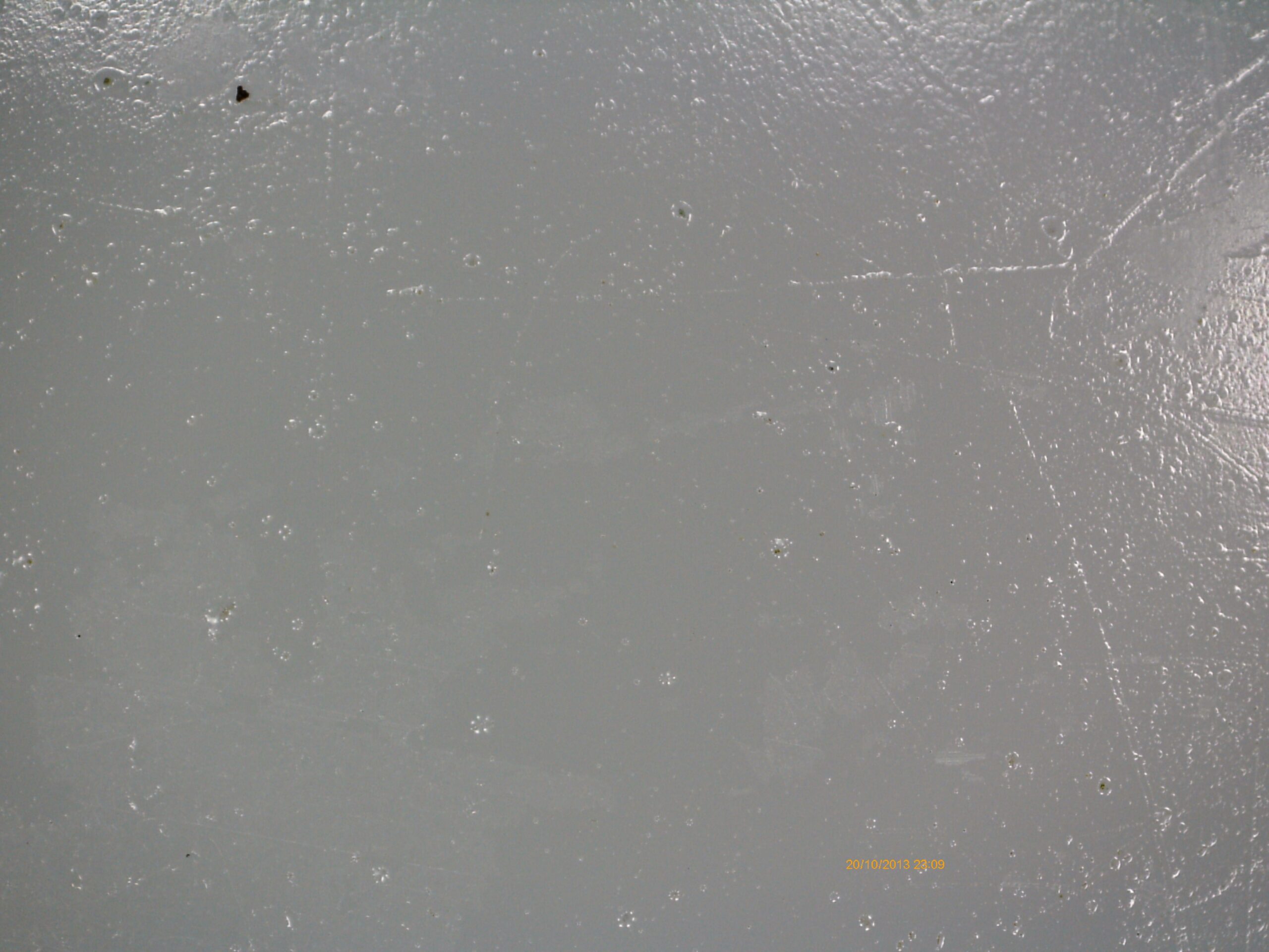
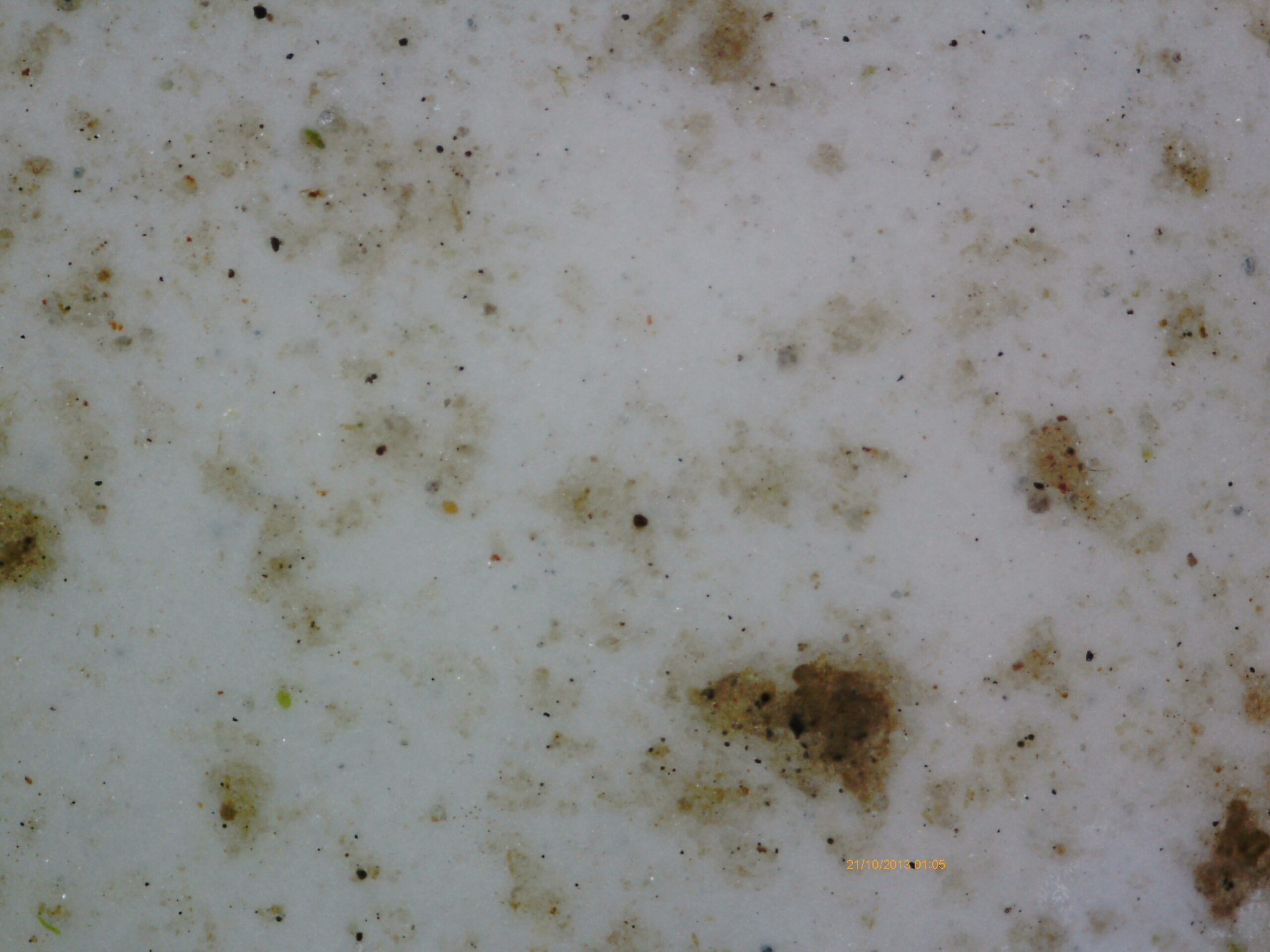
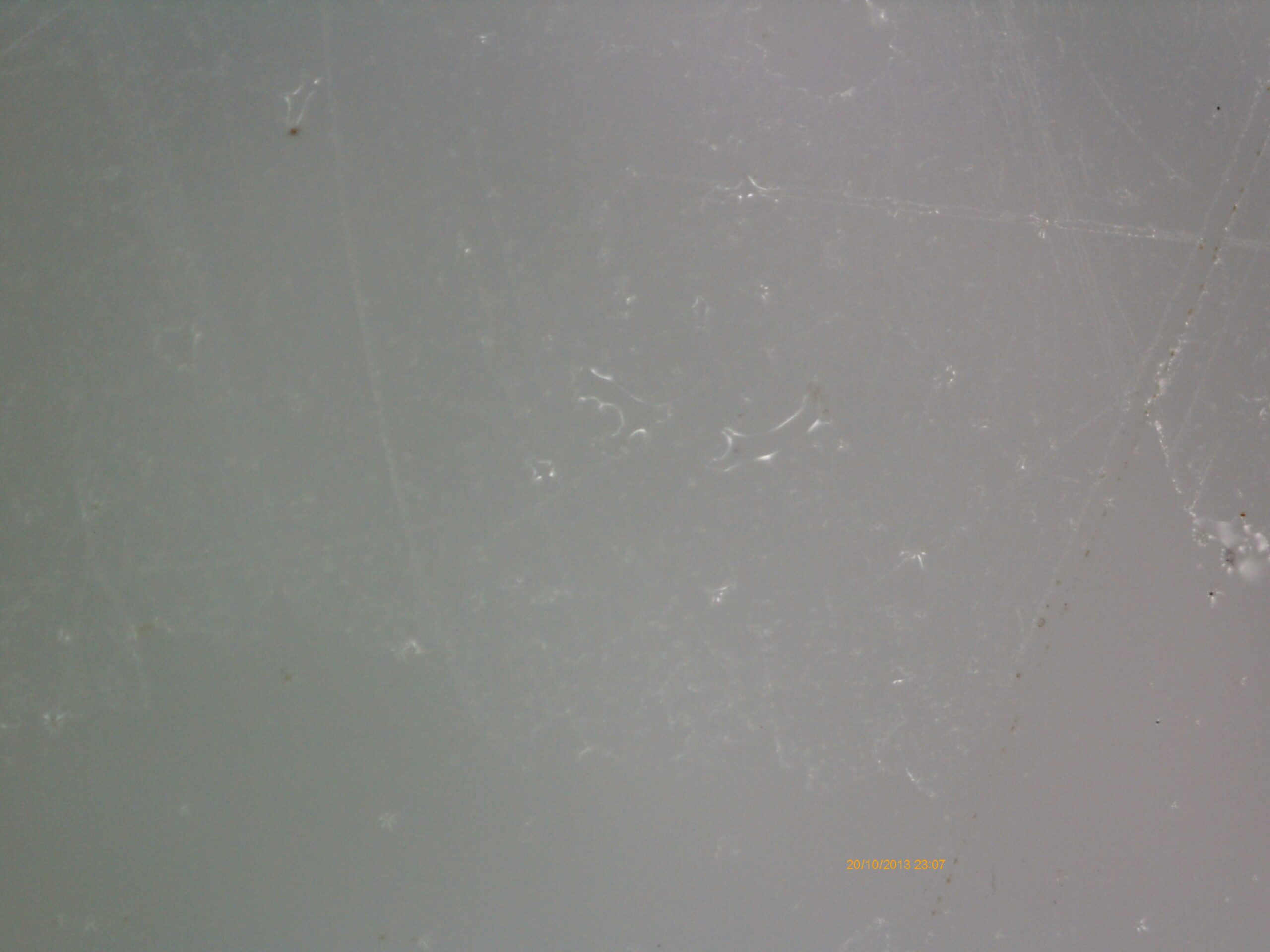
Figure 3 Sample images from biofouling growth on POM-C samples immersed under [Top] static conditions (x30 magnification, left and x190 magnification, right), and [Bottom] dynamic conditions at mid radial position (x30 magnification, left and x190 magnification, right)
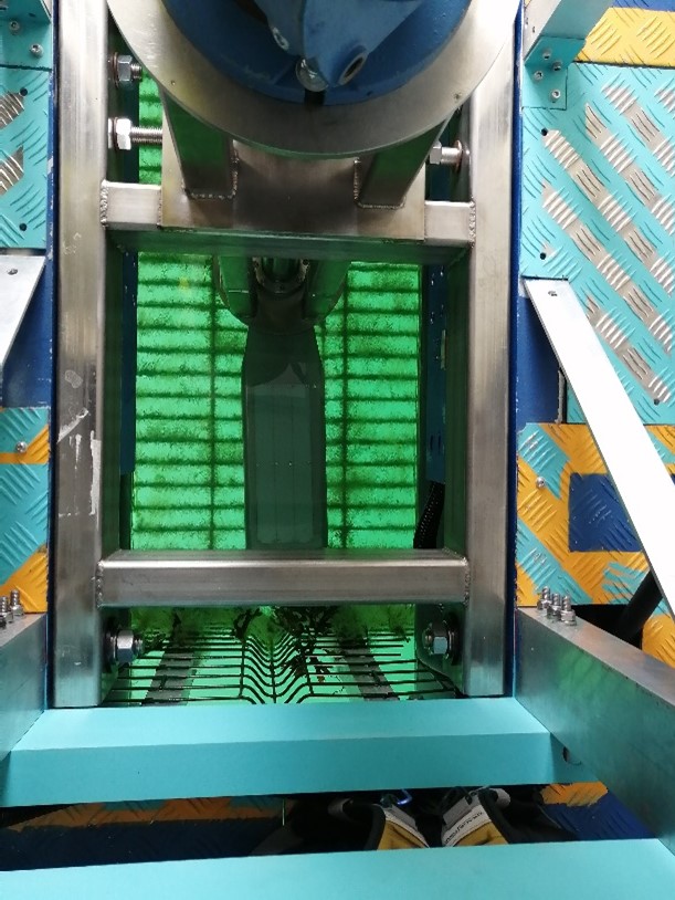
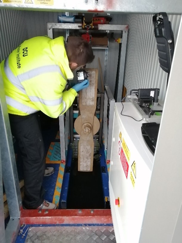
Figure 4: Turbine blade in lowered position with 1 set of recessed sample panels visible. Image 2 turbine in raised position with 2 sets of samples visible.
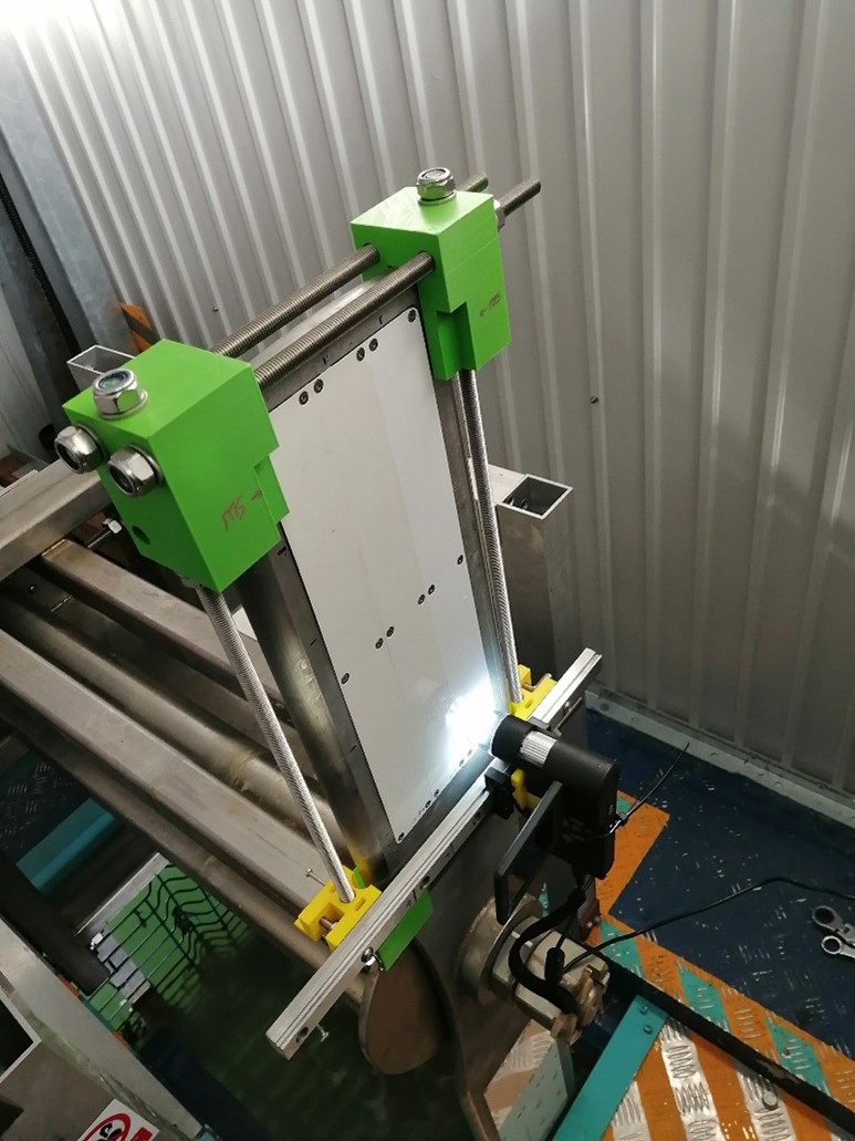
Figure 5: Raised blade with imaging system visible.
The results of the study on developing a biofouling behavioural model can be found in this report.