Last updated: 8 April 2021
Optimizing the turbine geometry requires rigorous investigation of hydrodynamic behaviour of blades and their interaction with the supporting structure and nacelle. SSPA has performed experimental tests on a scaled down model of turbine (1 :38) by measuring torque and thrust produced by the turbine in different Tip Speed Ratio, blade pitch angle and nacelle yaw angle.
The goal of this test campaign was to provide a baseline for furthur improvement of the blade design by evaluating the performance of the model turbine and measuring the flow field using Laser Doppler Velocimetry (LDV) method.
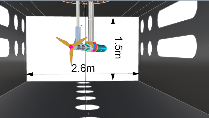
As shown in Figure 1, model was mounted inside the test section of the SSPA’s Cavitation tunnel with the size of 2.6mX1.5mX9.6m.
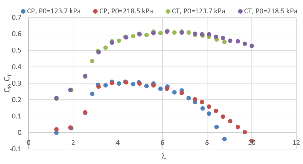
To investigate the cavitation effect on blades the tunnel operated under different static pressure conditions. Figure 2 shows the result of measured coefficient of power (CP) and coefficient of thrust (CT) in different Tip Speed Ratios (λ) for atmospheric and over pressured conditions.
The computational simulation of full-scale turbine has over predicted both CP and CT compared to the model test but this was expected as the Reynolds numbers could not be matched in model scale with 1 to 38 scale difference. The performance curve will be used as indicator for the suitable range of Tip Speed Ratios (λ) with highest coefficient of power (CP).
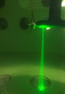
LDV measurements were performed at 3 different planes, before turbine, between the turbine plane and sward and after the sward. As shown in Figure 3, the 2-components continuous Laser beams were shined through the window at the bottom of the test section. The lasers measured instantaneous velocity of particles passing through a small control volume (50 microns) at the intersection of the beams. The velocities are treated statistically, rendering the velocity components of the flow in streamwise and cross-flow directions.
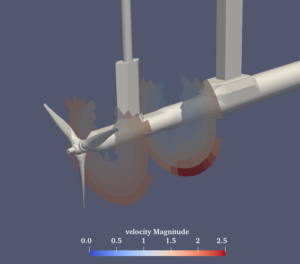
The average flow speed at different positions in these planes provide the flow condition after the turbine which will be the inflow into the opposite rotor. By traversing the laser beams in each plane velocity map of the flow field was produced. Figure 4 shows the velocity magnitude in two planes measured for the test rig in zero degree yaw angle.


